- Name
- Universal module with 3 In 3 Out
- Brand
- Everspring
- Features
- Feature Values Battery Quantity
- Documents
- Category Description File Manual_Primary_Lang
- Role type
- ROLE_TYPE_SLAVE_ALWAYS_ON
- User icon
- 0x0C07
- Categories
- Sensors, All Lighting Devices, On/Off Switches/Devices
- Product id
- 0x0001
- S2 classes
- S2_UNAUTHENTICATED, S2_AUTHENTICATED
- Device type
- Notification Sensor
- Oem version
- HW: 1 FW: 1.01:00.01
- Library type
- SLAVE_ENHANCED_232
- Product line
- Z-Wave Plus 500 Series
- Supports nwi
- Yes
- Installer icon
- 0x0C07
- Z wave version
- 6.81.06
- Frequency plans
- EU: 869.85MHz, 868.40MHz
- Manufacturer id
- 0x0060
- Product type id
- 0x0016
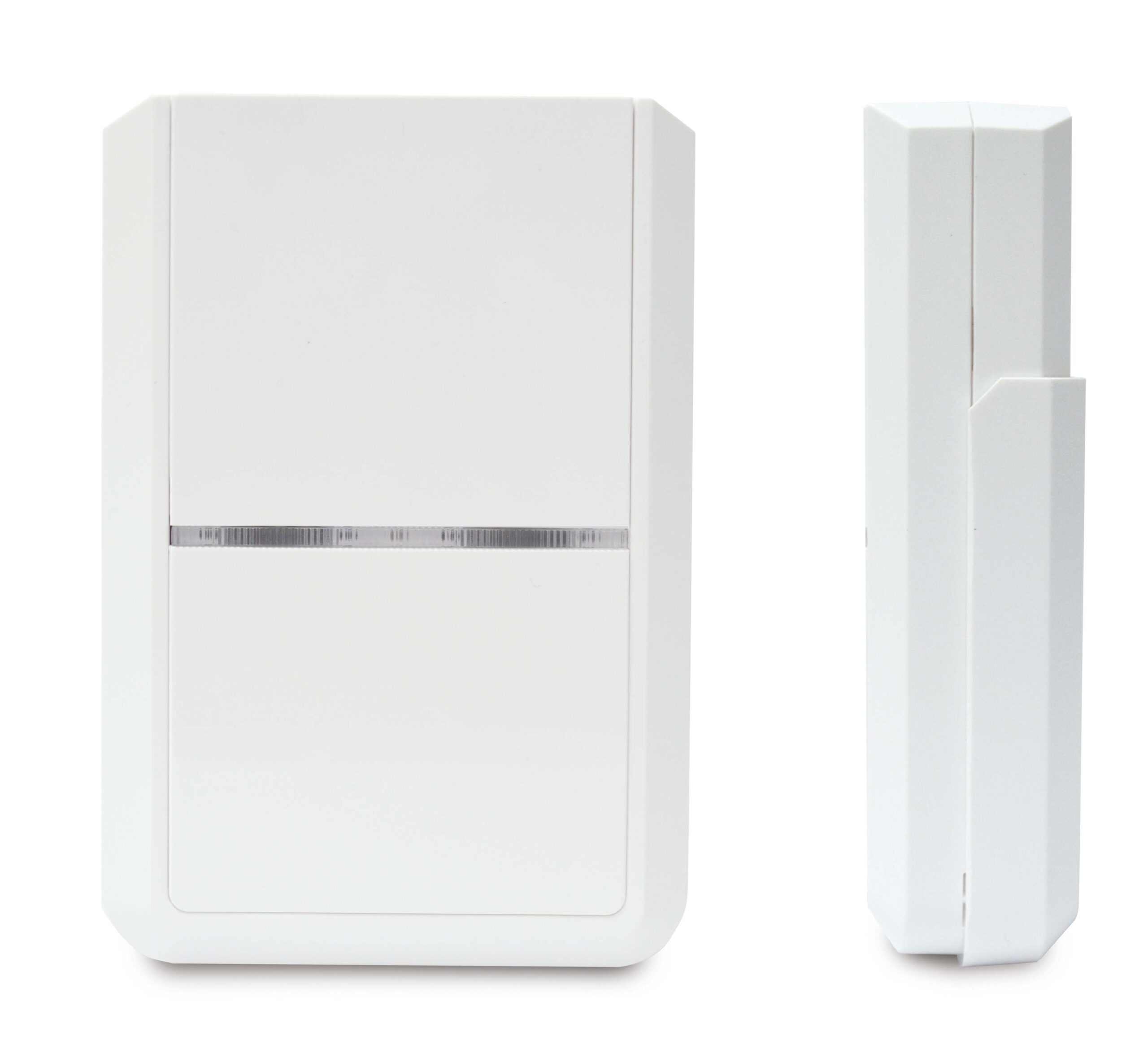
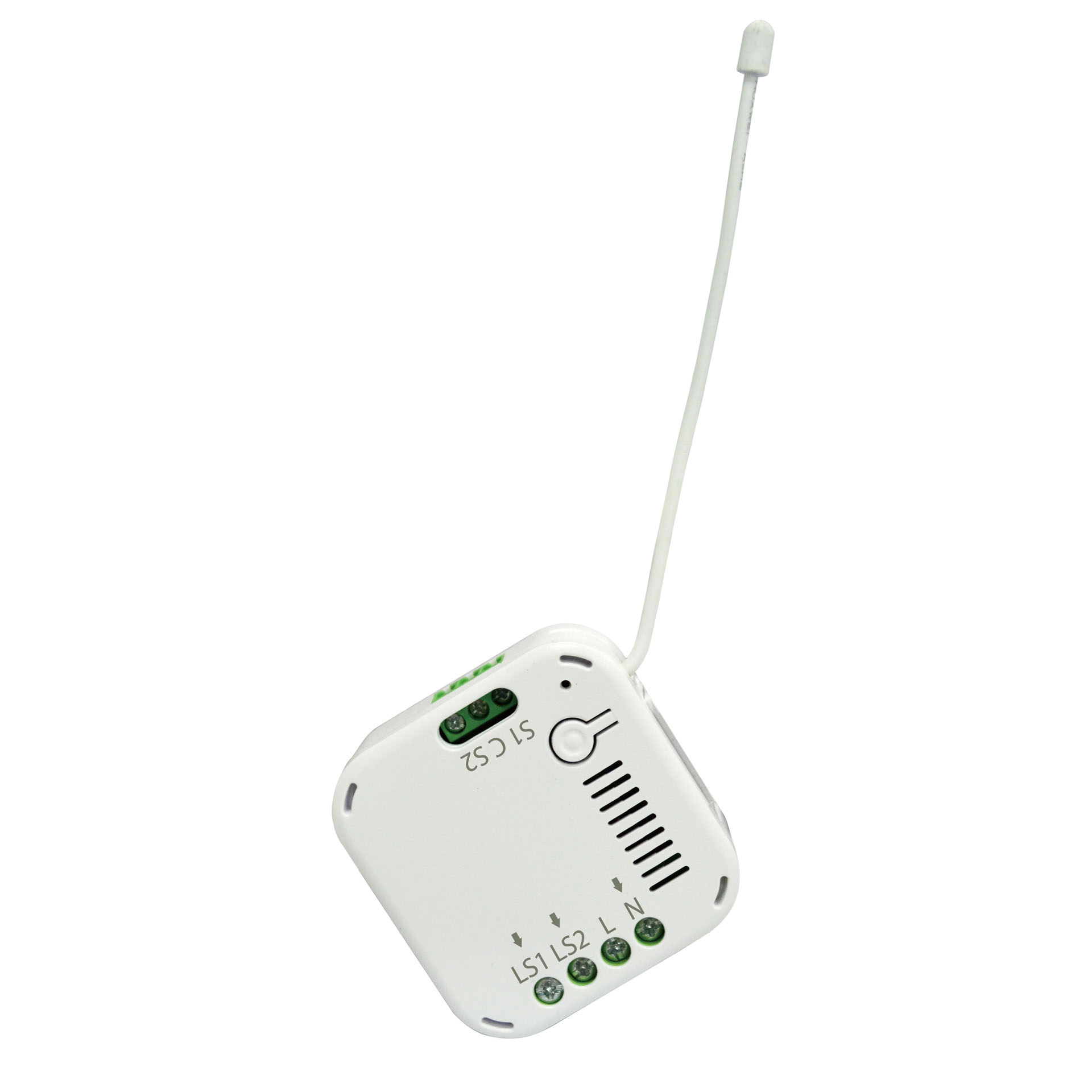
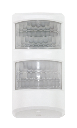
- Long description
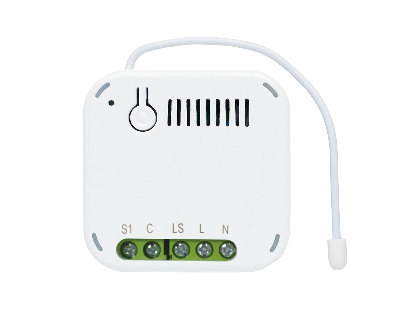
- The Universal Module is used to translate wired products into wireless Z-WaveTM protocol, integrating them into the Z-Wave network of a smarthome environment. It has 3 sets of input terminals and 3 sets of relay output. Through the Universal Module, the Z-Wave Controller can read the input signal from wired sensors and control the output of wired actuators. This product can be operated in any Z-Wave network with other Z-Wave certified devices from other manufactures. All mains operated nodes within the network will act as repeater regardless of vender to increase reliability of the network.
- Hardware platform
- SD3502
- Short description
- The Universal Module is used to translate wired products into wireless Z-WaveTM protocol, integrating them into the Z-Wave network of a smarthome environment. It has 3 sets of input terminals and 3 sets of relay output.
- Product identifier
- SA301-1
- Countries / regions
- European Union
- Supports smart start
- Yes
- Certification number
- ZC10-20056913
- Radio range z wave (m)
- 40
- Configuration parameters
- Parameter Number Name Description Format Size Min Value Max Value Default Value Parameter Values 3
- Supports explorer frames
- Yes
- Supported command classes
- Identifier Name Key Version COMMAND_CLASS_CONFIGURATION_V4
- Controlled command classes
- Identifier Name Key Version COMMAND_CLASS_BASIC
- Supported multilevel sensors
- Multilevel Sensor Type Voltage
- Supported notification types
- Notification Type Event / State Access Control
- Value 4 battery type value aaa 1.5 v color value white firmware updatable value updatable by consumer by rf association groups
- Group Number Maximum Nodes Supported End Point ID Group Name Description 1
- From to description 0 255 size =1, default value = 0x b4 (off after 180 secs) step of 1 sec, ‘0’ = remain on 11 in3 mode tell the device to active in3 mode 2 1 0 255 64 from to description 0 255 same as for in1 bit 7:corresponds to values in config 14, 15 4 in1 hi threshold voltage trigger level high threshold voltage level for trigger on (or trigger off, depending on mode). 2 1 0 255 25 from to description 0 255 size =1, default value = 0x19 (in1 trigger off when over 2500m v). step of 100m v. 6 in2 mode tell the device to active in2 mode 2 1 0 255 64 from to description 0 255 same as for in1 bit 7:corresponds to values in config 9, 10 10 in2 low threshold voltage trigger level low threshold voltage level for trigger on (or trigger off, depending on mode) 2 1 0 255 10 from to description 0 255 size =1 default value = 0x0 a (in2 trigger on when under 1000m v) 5 in1 low threshold voltage trigger level low threshold voltage level for trigger on (or trigger off, depending on mode). 2 1 0 255 10 from to description 0 255 size =1 default value = 0x0 a (in1 trigger on when under 1000m v) 7 out2 relay trigger on time relay 2 turn on period 2 1 0 255 5 from to description 0 255 size =1, default value = 0x05 (500ms) step of 100ms, ‘0’ = remain on 9 in2 hi threshold voltage trigger level high threshold voltage level for trigger on (or trigger off, depending on mode). 2 1 0 255 25 from to description 0 255 size =1, default value = 0x19 (in2 trigger off when over 2500m v). step of 100m v. 8 group 3 turn on time when triggered by in2 group 3 turn on period 2 1 0 255 180 from to description 0 255 size =1, default value = 0x b4 (off after 180 secs) step of 1 sec, ‘0’ = remain on 1 in1 mode tell the device to active in1 mode 2 1 0 255 64 from to description 0 255 size =1, default value = 0x40 bit 7:corresponds to values in config 4, 5 0 = trigger on when voltage under low threshold, trigger off when over hi threshold 1 = trigger on when voltage over hi threshold, trigger off when under low threshold bit 6:in1 3.3 v pull high on/off , 0 = off, 1 = on bit 5 4 : fixed at 0. bit 3:1 = activate out3 relay when in1 trigger bit 2:1 = activate out2 relay when in1 trigger bit 1:1 = activate out1 relay when in1 trigger bit 0:fixed at 0. 2 out1 relay trigger on time relay 1 turn on period 2 1 0 255 5 from to description 0 255 size =1, default value = 0x05 (500ms) step of 100ms, ‘0’ = remain on 17 tamper mode 0: no activate relay out 1: activate out1 relay when tamper 2: activate out2 relay when tamper 3: activate out1 & out2 relay when tamper 4: activate out3 relay when tamper 5: activate out1 & out3 relay when tamper 6: activate out2 & out3 relay when tamper 7: activate out1 & out2 & out3 relay when tamper 2 1 0 7 0 from to description 0 7 size =1, default value = 0x00 bit 3:1 = activate out3 relay when tamper bit 2:1 = activate out2 relay when tamper bit 1:1 = activate out1 relay when tamper texts