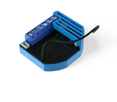
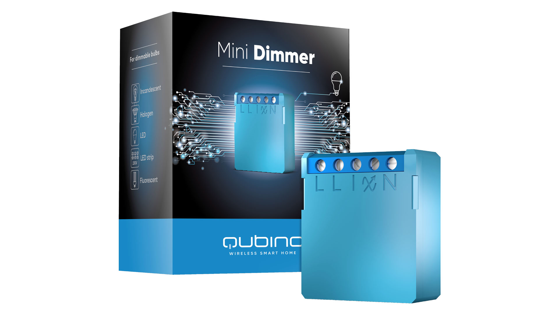
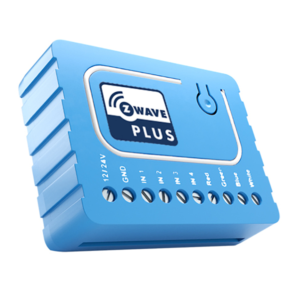
The Qubino Flush Dimmer 0-10V is a universal dimmer with a standard 0-10V output and a multi-function input, which may be a push button or switch, a potentiometer or a 0-10V signal. It also measures power consumption and supports the connection of a digital temperature sensor.
Want to buy adds it to your wish list and follows QUBINO for updates. I own it adds it to your collection.
Be the first to tag this page — tags appear right away. Try a theme, capability, or subject (e.g. WWII, heist, slow burn, time travel, A24).
Community
Be the first to start a thread about Qubino Flush Dimmer 0-10V
Threads post into the QUBINO community forum.
Sign in to start a thread in the QUBINO community.
Edit history
Loading edit history…
ZC10-17025435
Firmware & software
Firmware version
HW: 1 FW: 2.03:02.03
Hardware version
ZM5202
Identity & commercial
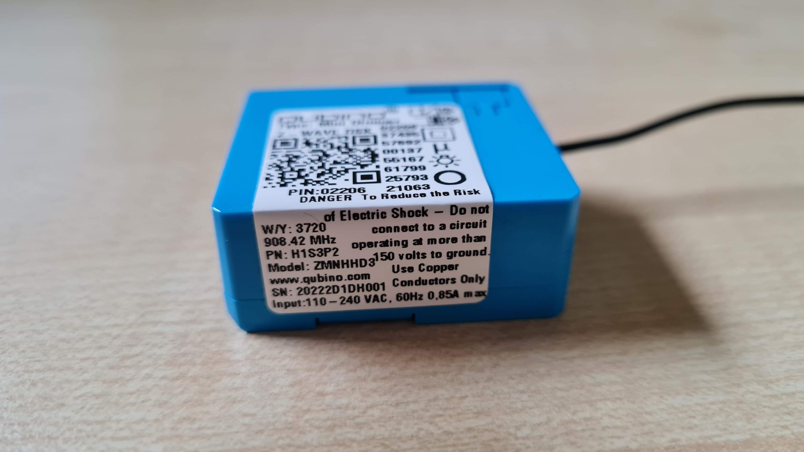
Model number
ZMNHVD2
Lifecycle
Status
Active
More specs
Name
Qubino Flush Dimmer 0-10V
Brand
QUBINO
Features
Feature Values Switch Load Capacity Watts
Documents
Category Description File Manual_Primary_Lang
Role type
ROLE_TYPE_SLAVE_ALWAYS_ON
User icon
0x1C00
Categories
All Lighting Devices, Dimming Lighting Devices
Product id
0x0053
Device type
Light Dimmer Switch
Oem version
HW: 1 FW: 2.03:02.03
Library type
SLAVE_ENHANCED_232
Supports nwi
Yes
Installer icon
0x1C00
Z wave version
6.51.08
Frequency plans
ANZ: 919.80MHz, 921.40MHz
Manufacturer id
0x0159
Product type id
0x0001
Long description
The Qubino Flush Dimmer 0-10V is a universal dimmer with a standard 0-10V output and a multi-function input, which may be a push button or switch, a potentiometer or a 0-10V signal. It also measures power consumption and supports the connection of a digital temperature sensor.
Hardware platform
ZM5202
Short description
The Qubino Flush Dimmer 0-10V is ideal for remotely dimming LED lights with low voltage ballast.
Product identifier
ZMNHVD2
Countries / regions
Australia
Certification number
ZC10-17025435
Configuration parameters
Parameter Number Name Description Format Size Min Value Max Value Default Value Parameter Values 250
Supports explorer frames
Yes
Supported command classes
Identifier Name Key Version COMMAND_CLASS_POWERLEVEL
Controlled command classes
Identifier Name Key Version COMMAND_CLASS_BASIC
Supported multilevel sensors
Multilevel Sensor Type Air temperature
Supported / controlled meter types
Meter Type Rate Type Description Electric meter
Value ac 140 w; dc 21 w sensors value air temperature supported meter type value electric energy switch type value push button electric load type value incandescent elv (electronic) dimmable led color value light blue switch load capacity current value 0,002 a (sinking current); 0,007 a (source current) association groups
Group Number Maximum Nodes Supported End Point ID Description 1
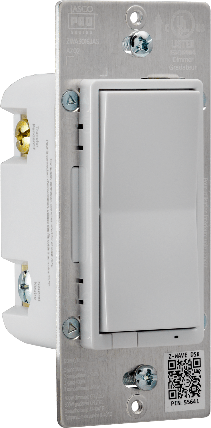
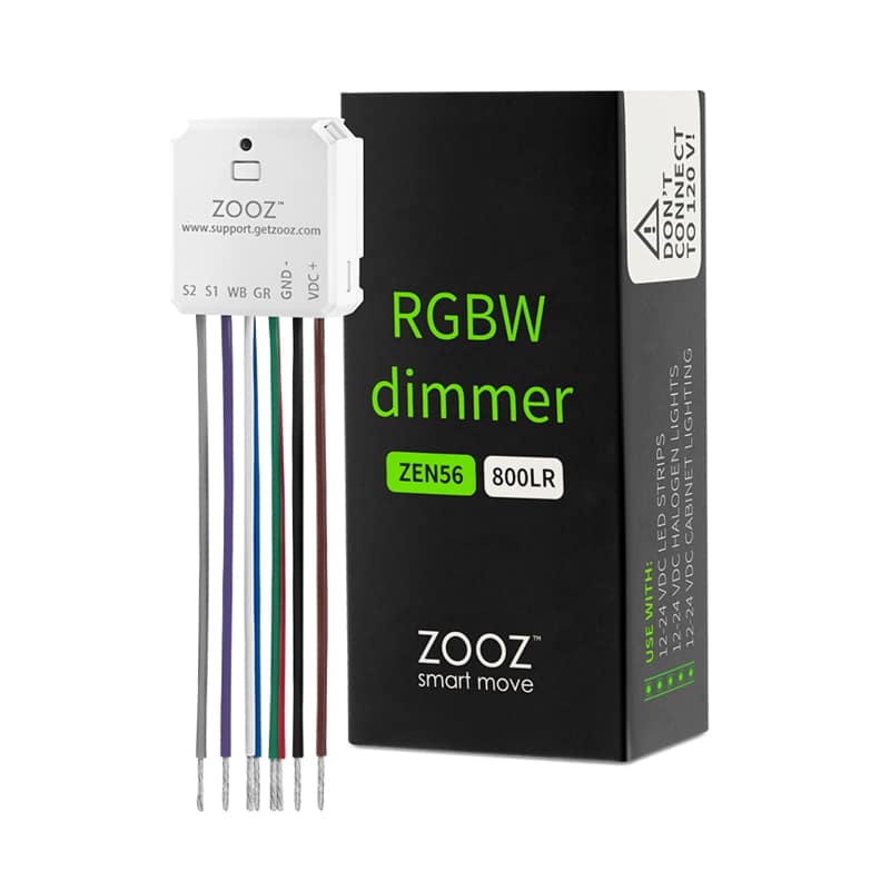
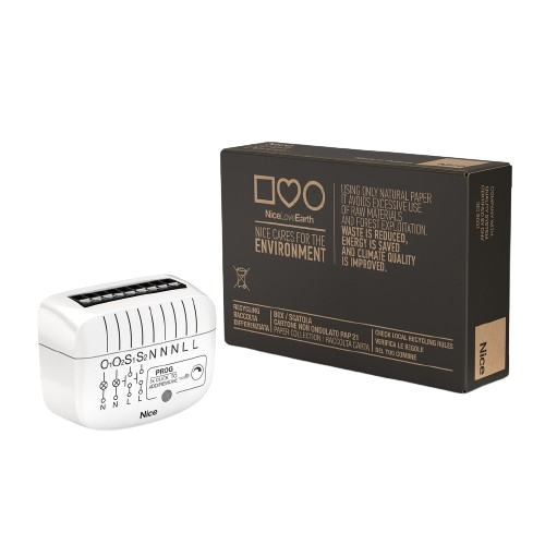
Similar Lighting
Current-generation and recently-released alternatives in the same category.
From to description 0 0 default value unsecure inclusion 1 1 secure inclusion 144 maximum sensor range value value that must correspond to maximum sensor range value. valid only if parameter 1 is set to values 3, 4 or 5). note: maximum value must not be lower than minimum value! 0 2 0 0 1000 from to description 10001 20000 value from 0,1 to 1000 (resolution 0,1) 1000 1000 default value 1000 = 100.0 degrees celsius / 100 lux / 100%rh 0 10000 value from 0 to 1000 (resolution 0,1) 1 input 1 switch type by this parameter the user can set input based on device type (switch, potentiometer, 0 10 v sensor,..). note: after parameter change to value 3, 4 or 5 first exclude module (without setting parameters to default value) then wait at least 30s and then re include the module! 0 1 0 0 0 from to description 1 1 bi stable switch type 3 3 0 10 v temperature sensor (regulated output) 4 4 0 10 v illumination sensor (regulated output) 2 2 potentiometer (flush dimmer 0 10 v is using set value the last received from potentiometer or from z wave controller) 0 0 default value mono stable switch type (push button) – button quick press turns between previous set dimmer value and zero) 5 5 0 10 v general purpose sensor (regulated output) 11 automatic turning off output after set time turns off the output after set time. 0 2 0 0 0 from to description 0 0 default value auto off disabled 1 32536 = 1second 32536 seconds auto off enabled with define time, step is 1 second 52 auto or manual selection this parameter is influencing on the software only when the value of parameter number 1 is set to value 3, 4 or 5. in manual mode regulation (how the input influence on output) is disabled. 0 1 0 0 0 from to description 0 0 default value manual 1 1 auto 53 pid value inside deadband note: when zero pid inside deadband is forced to zero. lastvalue means that pid remains on same level as was before entering into deadband. 0 1 0 0 0 from to description 0 0 default value pid value equal zero 1 1 pid value set to last value 54 pid deadband note: this parameter defines the zone where pid is not active. if the temperature difference between actual and setpoint is bigger than pid deadband, then the pid will start to regulate the system, otherwise the pid is zero or fixed. 0 1 0 0 1 from to description 1 1 default value 1 (1%) 0 100 0 100%, step is 1% 55 integral sampling time parameter defines the time between samples. on each sample the controller capture difference between sp act. 0 1 0 0 5 from to description 5 5 default value 5 (5s) 0 127 = 0s to 127s, step is 1s 57 i parameter the error is integrated (averaged) over a period of time, and then multiplied by a constant i, and added to the current control output. i represents the steady state error of the system and will remove setpoint / measured value errors. for many applications proportional + integral control will be satisfactory with good stability and at the desired setpoint. 0 2 0 0 1 from to description 1 1 default value 0 1000 i value, step is 1 58 d parameter the rate of change of the error is calculated with respect to time, multiplied by another constant d, and added to the output. the derivative term is used to determine a controller's response to a change or disturbance of the process temperature (e.g. opening an oven door). the larger the derivative term, the more rapidly the controller will respond to changes in the process value. 0 2 0 0 1 from to description 1 1 default value 0 1000 d value, step is 1 60 minimum dimming value note: the minimum level may not be higher than the maximum level! 1% min. dimming value is defined by z wave multilevel device class. when the switch type is selected as bi stable, it is not possible to dim the value between min and max. if switch multilevel set is set to the value “0”, the output is turned off. if switch multilevel set is set to the value “1”, the output is set to the minimum diming value. 0 1 0 0 1 from to description 1 1 default value = 1% (minimum dimming value) 1 98 = 1% 98%, step is 1%. minimum dimming values is set by entered value 61 maximum dimming value note: the maximum level may not be lower than the minimum level! 99% max. dimming value is defined by z wave multilevel device class. when the switch type is selected as bi stable, it is not possible to dim the value between min and max. 0 1 0 0 99 from to description 2 99 = 2% 99%, step is 1%. maximum dimming values is set by entered value. 99 99 default value = 99% (maximum dimming value) 65 dimming time (soft on/off) set value means time of moving the flush dimmer 0 10 v between min. and max. dimming values by short press of push button i1 or controlled through ui (basic set). 0 2 0 0 100 from to description 100 100 default value 100 = 1s 50 255 = 500 mseconds 2550 mseconds (2,55s), step is 10 mseconds 66 dimming time when key pressed time of moving the flush dimmer 0 10 v between min. and max dimming values by continues hold of push button i1 or associated device. 0 2 0 0 3 from to description 3 3 default value 3 = 3s 1 255 = 1 second 255 seconds 67 ignore start level this parameter is used with association group 3. a receiving device should respect the start level if the ignore start level bit is 0. a receiving device must ignore the start level if the ignore start level bit is 1. 0 1 0 0 0 from to description 0 0 default value respect start level 1 1 ignore start level 68 dimming duration this parameter is used with association group 3. the duration field must specify the time that the transition should take from the current value to the new target value. a supporting device should respect the specified duration value. 0 1 0 0 0 from to description 0 0 default value dimming duration according to parameter 66 1 127 from 1 to 127 seconds 110 temperature sensor offset settings set value is added or subtracted to actual measured value by sensor. 0 2 0 0 32536 from to description 32536 32536 default value offset is 0.0 degrees celsius 1 100 value from 0.1 degrees celsius to 10.0 degrees celsius is added to actual measured temperature 1001 1100 value from 0.1 degrees celsius to 10.0 degrees celsius is subtracted to actual measured temperature 120 digital temperature sensor reporting digital temperature sensor reporting if digital temperature sensor is connected, module reports measured temperature on temperature change defined by this parameter. available configuration parameters (data type is 1 byte dec): • default value 5 = 0,5°c change • 0 reporting disabled • 1 127 = 0,1°c 12,7°c, step is 0,1°c 0 1 0 0 5 from to description 5 5 default value = 0,5 degrees celsius change 0 0 reporting disabled 1 127 0,1 degrees celsius 12,7 degrees celsius, step is 0,1 degrees celsius 140 input i1 sensor reporting input i1 sensor reporting if analogue sensor is connected, module reports measured value on change defined by this parameter. 0 2 0 0 5 from to description 5 5 default value = 0,5 change 0 0 reporting disabled 1 10000 = 0,1 1000 step is 0,1 141 input i1 0 10 v reporting threshold parameter is associated with association group no. 2. below this value, the association no. 2 will report basic set 0x ff and above this value will report basic set 0x ff. basic set is reported only, when the input value changes for more than 10% (1 v). 0 1 0 0 5 from to description 5 5 default value = 5 (0,5 v) 1 100 0,1 10 v 143 minimum sensor range value value that must correspond to minimum sensor range value. valid only if parameter 1 is set to values 3, 4 or 5). available configuration parameters (data type is 2 byte dec): • default value 0 = 0.0°c / 0 lux / 0.0%rh • 0 10000 – value from 0 to 1000 (resolution 0,1) • 10001 – 20000 – value from 0,1 to 1000 (resolution 0,1) note: minimum value must not be higher than maximum value! 0 2 0 0 0 from to description 0 0 default value 0 = 0.0 degrees celsius / 0 lux / 0.0%rh 0 10000 value from 0 to 1000 (resolution 0,1) 10001 20000 value from 0,1 to 1000 (resolution 0,1)alue from 0,1 to 1000 (resolution 0,1) 10 activate / deactivate functions all on / all off flush dimmer 0 10 v module responds to commands all on / all off that may be sent by the main controller or by other controller belonging to the system. 0 2 0 0 255 from to description 2 2 all on active, all off is not active 255 255 default value all on active, all off active 0 0 all on is not active, all off is not active 1 1 all on is not active, all off active 56 p parameter the error is multiplied by a negative (for reverse action) proportional constant p, and added to the current output. p represents the band over which a controller's output is proportional to the error of the system. e.g. for a heater, a controller with a proportional band of 10 deg c and a setpoint of 100 deg c would have an output of 100% up to 90 deg c, 50% at 95 deg c and 10% at 99 deg c. if the temperature overshoots the setpoint value, the heating power would be cut back further. proportional only control can provide a stable process temperature but there will always be an error between the required setpoint and the actual process temperature. 0 2 0 0 100 from to description 0 1000 p value, step is 1 100 100 default value texts